Layer 2 vs. Layer 3 Switches
In Part 2, we established that switches handle local traffic and routers handle everything else. That framing is useful—and it’s also incomplete.
Modern networks don’t draw a clean line between “this is what a switch does” and “this is what a router does.” In most enterprise environments, the device doing the routing between VLANs isn’t a router at all. It’s a switch, just one that happens to understand IP addresses. This is the Layer 3 (L3) switch, and understanding how it differs from a traditional switch operating within L2 is at the core of modern network design.
This part breaks down both device types: what they do, how they make forwarding decisions, and where each belongs in a network.
What a Layer 2 Switch Does
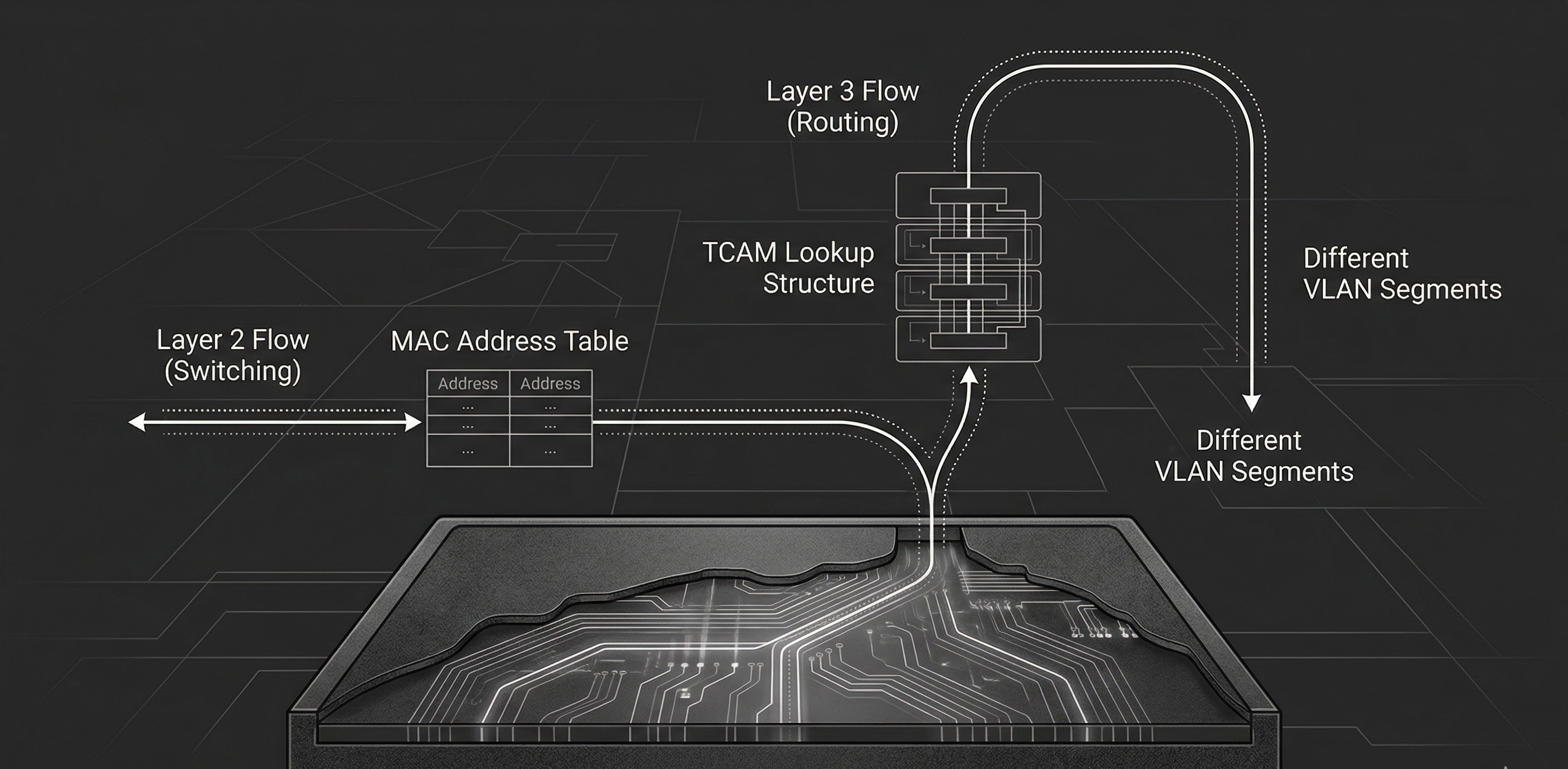
A Layer 2 switch operates at the Data Link layer of the OSI model. Its job is straightforward: receive frames, learn source MAC addresses, and forward frames to the correct port based on the destination MAC address.
As we discussed last time, this is made possible by the MAC address table1. This table keeps a record of which MAC addresses belong to which switch ports. When a frame arrives, the switch records the source MAC and the port it came in on. When it needs to forward, it simply looks up the destination MAC in the table and sends the frame out the matching port.
If the destination MAC isn’t found, referred to as an unknown unicast, the switch will flood the frame out every port in the VLAN except the source port2. Broadcast and multicast frames are also flooded by default. This is the behavior we touched on in Part 2, and it’s why a switch with no entries in its MAC table is logically equivalent to a hub.
VLANs: Logical Segmentation at Layer 2
Layer 2 switches support VLANs (Virtual Local Area Networks), which allow you to divide a single physical switch into multiple isolated broadcast domains3. Devices in VLAN 10 cannot communicate with devices in VLAN 20, even if they’re plugged into the same physical switch, unless traffic is explicitly routed between them4.
VLANs are defined by the IEEE 802.1Q standard. When a frame needs to traverse a trunk link—a link carrying traffic for multiple VLANs—the switch inserts a 4-byte 802.1Q tag into the Ethernet header5. This tag contains:
- TPID (Tag Protocol Identifier)—16 bits, set to
0x8100, identifying the frame as being 802.1Q-tagged. - PCP (Priority Code Point)—3 bits, used for QoS prioritization (IEEE 802.1p).
- DEI (Drop Eligible Indicator)—1 bit, indicates whether the frame can be dropped under congestion.
- VID (VLAN Identifier)—12 bits, identifying the VLAN itself. This gives us a range of 0–4095, though VLANs 0 and 4095 are reserved, leaving 1-4094 usable6.
On the other end of the trunk, the receiving switch reads the VID, determines which VLAN the frame belongs to, and forwards accordingly. When a frame exits through an access port—a port assigned to a single VLAN—the tag is stripped. The end device never sees it.
This is the extent of a Layer 2 switch’s world. It understands MAC addresses, VLANs, and frames. Ask it to get a packet from VLAN 10 to VLAN 20, and it will stare at you blankly. That requires routing, and as we learned routing requires L3.
The Inter-VLAN Routing Problem
VLANs solve broadcast domain isolation beautifully, but they create a new problem: devices in different VLANs can’t talk to one another. Since each VLAN is its own broadcast domain with its own subnet, typically7, traffic between VLANs requires a L3 forwarding decision—a routing decision.
Historically, this meant plugging a physical router into the switch. Within CCNA’s scope you need to understand two approaches:
Router-on-a-Stick
In a router-on-a-stick configuration, a single physical router interface connects to a switch via a trunk link. The router creates sub-interfaces—logical interfaces, each assigned to a different VLAN and configured with an IP address that serves as the default gateway for that VLAN.
Traffic flow looks something like this:
- Host A in VLAN 10 sends a packet destined for Host B in VLAN 20.
- Host A’s default gateway is the router’s sub-interface for VLAN 10.
- The frame travels to the switch, crosses the trunk link to the router.
- The router receives the frame on the VLAN 10 sub-interface, makes a routing decision, and sends the packet down the same physical link on the VLAN 20 sub-interface.
- The switch receives the frame (now tagged for VLAN 20) and forwards it to Host B.
This is the key delineation to understand—the sub-interfaces described are logical. Make note that the physical copper the frames traverse remains the same.
This works, and for small networks it’s perfectly adequate. But notice the bottleneck: all inter-VLAN traffic funnels through a single physical link to the router and back8. The router performs forwarding in software on a general-purpose CPU9. Scale this to dozens of VLANs with heavy inter-VLAN traffic and you’ve got yourself into quite a pickle.
SVI-Based Routing on a Layer 3 Switch
This is where Layer 3 switches change the game.
A Layer 3 switch is a switch that can also route. Instead of sending inter-VLAN traffic out to an external router, the switch routes it internally using Switched Virtual Interfaces (SVIs).
An SVI is a virtual Layer 3 interface that represents a VLAN on the switch. You configure an SVI for each VLAN that needs routing, assign it an IP address, and that address becomes the default gateway for all devices in that VLAN. When a packet needs to move from VLAN 10 to VLAN 20, the L3 switch handles the routing decision internally—no external router required, no hairpinning traffic out a trunk link and back10.
The difference in traffic flow is significant. With router-on-a-stick, inter-VLAN packets travel: host -> switch -> router -> switch -> host. With a Layer 3 switch using SVIs, it’s: host -> switch (routes internally) -> host. One fewer hop, no trunk bottleneck, and the routing happens in hardware.
How Layer 3 Switches Route in Hardware
This is the part that makes Layer 3 switches fundamentally different from routers; not in what they do, but in how they do it.
Traditional routers forward packets using a general-purpose CPU. That CPU reads each packet header, performs a routing table lookup, and decides where to send it. This works, but it introduces latency and has throughput limitations. Software-based forwarding is flexible, but it doesn’t scale to millions of packets per second. Layer 3 switches use ASICs (Application-Specific Integrated Circuits): purpose-built silicon designed to perform forwarding at wire speed11. The key enabling technology is TCAM (Ternary Content-Addressable Memory).
Here’s the short version of how it works:
- A CAM (Content-Addressable Memory) table stores exact-match lookups. You give it a MAC address, it returns the port. This is how Layer 2 forwarding decisions are made.
- A TCAM extends this with a third state: don’t care (in addition to 0 & 1). Where CAM requires every bit to match exactly, TCAM lets you mark trailing bits as “don’t care,” which means a single entry can represent an entire subnet. A route like
192.168.1.0/24becomes a TCAM entry where the first 24 bits must match and the remaining 8 are masked as don’t care. When a packet arrives, the TCAM compares the destination IP against all entries simultaneously. Multiple entries can match, but because entries are stored in order of prefix length, the hardware returns the first hit, which is the longest prefix match12. This is exactly what IP routing needs. You give it a destination IP, it matches against route prefixes stored in the TCAM, and returns the next hop and exit interface.
Because TCAM lookups occur in constant time, a Layer 3 switch can route packets at the same time it switches frames12. No CPU bottleneck. No added latency. The packet enters a port, the ASIC performs both the Layer 2 and the Layer 3 lookup, and the packet exits the correct port—all at wire speed.
This is why Layer 3 switches dominate enterprise LAN design. They give you the forwarding performance of a switch with the routing capability of a router.
Routed Ports
SVIs aren’t the only way a Layer 3 switch performs routing. Layer 3 switches also support routed ports: physical switch ports that are converted from Layer 2 (switching) mode to Layer 3 (routing) mode.
A routed port behaves like a router interface. It gets an IP address, participates in routing protocols, and forwards packets based on IP, not MAC. It does not belong to a VLAN, does not participate in Spanning Tree, and does not carry trunk tags.
When do you use a routed port instead of an SVI?
- Point-to-point links between Layer 3 switches: When two switches need a direct IP-routed link, a routed port is cleaner. No VLAN to manage, no trunk to configure—just a direct Layer 3 connection.
- Uplinks to routers or firewalls: If the connected device expects a plain IP interface, a routed port is the natural choice.
When do you use an SVI instead?
- When multiple physical ports share the same subnet: An SVI represents a VLAN, and a VLAN can span many ports. If you need 24 ports in VLAN 10 and want those devices to route to VLAN 20, an SVI is the only option. A routed port is a single physical port, i.e. by definition it cannot serve multiple ports in the same subnet13.
In practice, most inter-VLAN routing in enterprise environments uses SVIs. Routed ports are reserved for specific point-to-point connections.
Layer 2 vs. Layer 3: When to Use Which
Not every switch in a network needs to be L3. Understanding when each type is appropriate is as important as understanding how they work.
Use a Layer 2 switch when:
- You need a simple, cost-effective access layer device. Layer 2 switches are less expensive and perfectly adequate for connecting end devices to the network.
- Routing is handled elsewhere. If a L3 switch or router upstream handles all inter-VLAN routing, access-layer switches can remain L2.
- The network is small and flat. A home office, small business, or lab with one or two VLANs may not justify the cost of Layer 3 switching.
Use a Layer 3 switch when:
- You need inter-VLAN routing. This is the primary use case. If your network has multiple VLANs and devices need to communicate across them, a Layer 3 switch is the standard solution.
- You need routing performance at scale. Hardware-based routing through ASICs handles high-throughput environments that a router-on-a-stick would not be equipped to handle.
- You’re building a distribution or core layer. In hierarchical network designs (two-tier and three-tier architectures), Layer 3 switches typically occupy the distribution and core layers, where fast routing between segments is needed14.
| Capability | Layer 2 Switch | Layer 3 Switch |
|---|---|---|
| Frame forwarding (MAC) | ✅ | ✅ |
| VLAN support | ✅ | ✅ |
| 802.1Q trunking | ✅ | ✅ |
| Spanning Tree | ✅ | ✅ |
| IP routing (inter-VLAN) | ❌ | ✅ |
| SVIs | Management only | Routing per VLAN |
| Routed ports | ❌ | ✅ |
| Dynamic routing protocols | ❌ | ✅ (OSPF, BGP, etc.) |
| Hardware-based IP routing (TCAM) | ❌ | ✅ |
A Layer 3 switch can do everything a Layer 2 switch can do, functionality speaking. The reverse is not true. The cost difference is the primary reason Layer 2 switches still exist in the access layer, but that gap narrows with every new generation of hardware.
Key Takeaways
- Layer 2 switches forward frames using MAC addresses: They build a MAC address table from incoming traffic and use it to forward frames to specific ports. They understand VLANs but cannot route between them.
- Layer 3 switches add IP routing to switching: Using SVIs and routed ports, they route packets between VLANs internally—no external router needed.
- Hardware-based routing is the key differentiator: Layer 3 switches use ASICs and TCAM to perform routing lookups at wire speed, largely eliminating the CPU bottleneck that traditional routers face.
- Router-on-a-stick works but doesn’t scale: For small networks it’s fine, but funneling all inter-VLAN traffic through a single router link creates a bottleneck.
- SVIs and routed ports serve different purposes: SVIs route traffic for VLANs spanning multiple ports. Routed ports convert a switch port into a point-to-point interface.
- Use Layer 2 at the access layer, Layer 3 at distribution and core: This is the standard in network design, and understanding when each switch type is appropriate is at the core of network design.
In Part 4, we shift from forwarding devices to security devices: firewalls and intrusion prevention systems, and examine how they protect the traffic that switches and routers move.
References
- Cisco Systems. (2023). Classification TCAM with Cisco CloudScale ASICs for Nexus 9000 Series Switches. Cisco. Link
- Cisco Systems. (2024). CCNA Exam Topics (200-301 v1.1). Cisco Learning Network. Link
- Cisco Systems. (2024). Configure Inter-VLAN Routing with Catalyst Switches. Cisco. Link
- Cisco Systems. (2024). Configuring Layer 3 Interfaces. Cisco Nexus 5000 Series. Link
- Edgeworth, B., Garza Rios, B., Gooley, J., & Hucaby, D. (2020). CCNA 200-301 Official Cert Guide, Volume 1. Cisco Press.
- IEEE Standards Association. (2018). IEEE 802.1Q-2018 — Bridges and Bridged Networks. IEEE. Link
- IEEE Standards Association. (2020). IEEE 802.1AX-2020 — Link Aggregation. IEEE. Link
- IEEE Standards Association. (2022). IEEE 802.3 — Ethernet. IEEE. Link
- IETF. (2006). RFC 4541 — Considerations for IGMP and MLD Snooping Switches. IETF. Link
- Cisco Systems. (2024). Understand Express Forwarding (CEF). Cisco. Link
- Cisco Systems. (2024). Configuring SDM Templates. Cisco Catalyst 9500 Series. Link
- Cisco Systems. (2024). Spanning Tree Protocol. Cisco. Link
Footnotes
-
The MAC address table is stored in CAM (Content-Addressable Memory)—specialized hardware that performs exact-match lookups in a single clock cycle. You’ll often hear it called the CAM table, especially in Cisco documentation and CCNA study material. The terms are interchangeable: “MAC address table” describes what the table contains; “CAM table” describes how it’s implemented in hardware. CAM entries include the MAC address, the associated port, and the VLAN, and they age out after a configurable timer (300 seconds by default on Cisco—other vendors use different defaults, so this value is platform-specific rather than universal). If the table fills—whether organically or via a deliberate CAM overflow attack (MAC flooding)—the switch reverts to flooding all unknown unicast traffic, effectively becoming a hub. Port security (limiting allowed MACs per port) is the primary mitigation. We covered this briefly in Part 2 and will revisit it in Part 20. ↩
-
The term “flooding” applies differently depending on the frame type. Unknown unicast flooding occurs when the switch has no MAC address table entry for the destination—the frame is sent out every port in the VLAN except the ingress port. This is a temporary condition; once the destination host responds, the switch learns its MAC and subsequent frames are forwarded directly. Broadcast frames (destination MAC
FF:FF:FF:FF:FF:FF) are always flooded to every port in the VLAN—this is by design, not a fallback behavior, and is how protocols like ARP and DHCP function. Multicast frames are flooded by default on Layer 2 switches that lack multicast optimization. Switches with IGMP snooping enabled can constrain multicast traffic to only the ports that have joined the multicast group, significantly reducing unnecessary flooding. Without IGMP snooping, multicast is treated identically to broadcast. The distinction matters for troubleshooting and for understanding why a “quiet” network can suddenly generate unexpected traffic—a single unknown unicast destination or a burst of multicast from a misconfigured application can flood an entire VLAN. ↩ -
VLANs will get their own dedicated post in Part 21. For now, think of a VLAN as a way to create separate networks on the same physical switch. Devices in the same VLAN communicate freely; devices in different VLANs cannot—unless a Layer 3 device routes between them. A single switch can host dozens of VLANs simultaneously, each with its own broadcast domain. Configuration, access ports, voice VLANs, and default VLANs are all covered when we get there. ↩
-
VLAN isolation is a logical control, not an absolute security boundary. Two well-documented Layer 2 attacks can bypass VLAN segmentation: switch spoofing, where an attacker negotiates a trunk link (typically via DTP—Dynamic Trunking Protocol) and gains access to traffic on all VLANs carried by that trunk; and double tagging, where an attacker crafts a frame with two 802.1Q tags—the outer tag matching the native VLAN is stripped by the first switch, and the inner tag forwards the frame into a different VLAN. Double tagging is one-directional (the attacker can send but not receive replies on the target VLAN) and relies on the native VLAN being misconfigured. Mitigations are straightforward and CCNA-relevant: disable DTP on all access ports (
switchport mode accessandswitchport nonegotiate), change the native VLAN to an unused VLAN, and explicitly tag the native VLAN on trunks (vlan dot1q tag nativeon Cisco). These attacks and their countermeasures are covered in depth in Part 20. For the curious: more advanced VLAN escape techniques—such as exploiting VTP (VLAN Trunking Protocol) vulnerabilities or leveraging CDP/LLDP information leakage for reconnaissance—exist but are increasingly rare in hardened environments and go beyond the CCNA. ↩ -
The 802.1Q tag is inserted between the source MAC address and the EtherType/Length field in the Ethernet header. This increases the maximum frame size from 1518 bytes to 1522 bytes for tagged frames, which matters for MTU calculations. Some older equipment that doesn’t expect 802.1Q tags may drop oversized frames—increasingly rare in modern networks but still a potential gotcha in brownfield environments. Cisco once used a proprietary trunking protocol called ISL (Inter-Switch Link) that encapsulated the entire frame rather than inserting a tag. ISL is obsolete and no longer on the CCNA exam, but you may encounter references in older documentation. For the curious: Q-in-Q (IEEE 802.1ad), which stacks two 802.1Q tags for service provider VLAN isolation, is CCNP ENCOR territory. ↩
-
The 12-bit VID field gives a theoretical maximum of 4,096 VLANs. VID 0 is reserved for priority tagging (the frame carries QoS priority but no VLAN assignment), and VID 4095 is reserved per the standard. On Cisco platforms, VLANs 1002–1005 are reserved for legacy Token Ring and FDDI support and cannot be deleted, and the extended VLAN range (1006–4094) has configuration restrictions depending on VTP mode. In practice, most networks use far fewer VLANs than the maximum, but large campus or data center environments with multi-tenancy can approach the limit. For the curious: VXLAN (Virtual Extensible LAN), which uses a 24-bit identifier to support over 16 million logical segments, is the modern answer to VLAN scalability and is covered in CCNP ENCOR. ↩
-
The one-VLAN-one-subnet mapping is a design best practice, not a protocol requirement. A VLAN is a Layer 2 construct—it doesn’t inherently “have” a subnet. You can create a VLAN and never assign IP addressing to it (e.g., a parking VLAN for unused ports). You can also place the same subnet on two different VLANs, though this creates two isolated halves of the same address space that can’t communicate via ARP—a broken configuration in nearly every scenario. The convention exists because it produces clean, predictable routing boundaries: one VLAN, one subnet, one SVI or sub-interface, one default gateway. When you see “each VLAN has its own subnet” in CCNA material, it’s describing the expected design pattern, not a technical constraint enforced by 802.1Q. ↩
-
Strictly speaking, the “single link” bottleneck can be mitigated with EtherChannel (also called LAG—Link Aggregation Group, standardized as IEEE 802.3ad/802.1AX). EtherChannel bundles multiple physical links into one logical link, increasing aggregate bandwidth and providing redundancy. A router-on-a-stick topology using an EtherChannel trunk still routes in software on the router’s CPU, so the per-packet forwarding bottleneck remains—but the link-bandwidth bottleneck is reduced. In practice, if inter-VLAN traffic volume justifies EtherChannel to a router, it’s usually a sign the design should migrate to a Layer 3 switch with SVIs instead. EtherChannel configuration and load-balancing algorithms are covered in Part 8. ↩
-
This is a generalization that holds for the type of routers you’ll encounter at the CCNA level. In reality, modern enterprise and service provider routers (Cisco ASR, Juniper MX, etc.) also use ASICs and dedicated forwarding silicon—they are not purely software-based. The distinction between “routers route in software” and “switches route in hardware” is increasingly a legacy framing. What remains true is that within a LAN context, Layer 3 switches are optimized for high-port-density, high-throughput inter-VLAN routing in ways that traditional routers are not. Routers excel at WAN connectivity, complex policy routing, and protocol support that switches typically don’t handle. The roles overlap more than exam material suggests. For the curious: understanding where the router/switch hardware boundary has blurred—NPUs, merchant silicon, disaggregated networking—goes well beyond the CCNA. ↩
-
The performance advantage of SVI-based routing comes with a security trade-off worth understanding. When a Layer 3 switch routes traffic between VLANs internally, that traffic never traverses a firewall or intrusion prevention system unless the network is explicitly designed to force it through one (via policy-based routing, VLAN ACLs, or a service insertion architecture). In a router-on-a-stick design, inter-VLAN traffic naturally passes through the router—where firewall rules or inspection can be applied. With SVI-based routing, you gain speed but lose a natural inspection point. In security-sensitive environments, this means either (a) applying VLAN ACLs directly on the Layer 3 switch to filter inter-VLAN traffic, (b) steering sensitive traffic through a dedicated firewall using route manipulation, or (c) accepting the trade-off for performance-critical segments while inspecting higher-risk VLAN pairs. This is a real design consideration in enterprise networks and is revisited when we cover firewall placement in Part 4. For the curious: SD-Access and Cisco TrustSec take a different approach by applying security policy based on group tags (SGTs) rather than network topology—allowing inline enforcement without hairpinning traffic to a firewall. This is CCNP ENCOR and beyond. ↩
-
Wire speed (also called line rate) means the device can forward traffic at the maximum theoretical throughput of all its ports simultaneously, with no packet loss due to processing bottleneck. A 48-port Gigabit switch operating at wire speed can handle 48 Gbps of full-duplex traffic without dropping frames. Not all switches marketed as “Layer 3” achieve true wire speed for routed traffic—it depends on the ASIC capability and TCAM capacity. Always check the vendor’s forwarding performance specifications, particularly the distinction between Layer 2 switching capacity and Layer 3 routing capacity. ↩
-
To illustrate concretely: consider two routes in the TCAM —
192.168.1.0/24and192.168.1.128/25. In binary, the/24entry stores the first 24 bits as exact match (11000000.10101000.00000001) and marks the remaining 8 bits asX(don’t care). The/25entry stores 25 exact bits (11000000.10101000.00000001.1) and marks only 7 as don’t care. A packet destined for192.168.1.200(11000000.10101000.00000001.11001000) matches both entries — the/24because all 24 fixed bits match, and the/25because all 25 fixed bits match (the 25th bit is1). The TCAM evaluates all entries in parallel in a single clock cycle, but entries are ordered by prefix length (longest first). The/25sits at a lower index than the/24, so the hardware returns it as the first match — guaranteeing the longest prefix wins. A software router achieves the same result by walking a trie or performing a binary search, which scales with table size. TCAM does it in constant time — O(1) — regardless of how many routes are stored, because every entry is evaluated simultaneously in silicon. Without the don’t-care state, you’d need a separate exact-match entry for every possible destination IP rather than one entry per prefix — obviously impossible for a routing table. That said, this is the ideal case, and TCAM is a finite and expensive resource. Every routing table entry, ACL rule, QoS policy, and multicast entry consumes TCAM space. On lower-end switches, capacity is limited, and administrators must make trade-offs about how to allocate it—a process Cisco calls SDM (Switching Database Manager) templates. When TCAM overflows, the switch falls back to software forwarding via the CPU, which dramatically reduces performance. TCAM overflow isn’t the only cause of CPU-based forwarding. Certain features—DHCP snooping, dynamic ARP inspection (DAI), IP source guard, and complex ACLs that exceed hardware resources—can cause specific packets to be punted to the CPU for processing even when TCAM has available capacity. Control plane traffic (routing protocol updates, SNMP, SSH) is always CPU-bound. In all these cases, forwarding for the affected traffic drops well below wire speed. This is a real operational concern in environments with large routing tables, complex ACL configurations, or aggressive Layer 2 security policies. For the curious: TCAM carving, SDM templates, CEF adjacency tables, and CoPP (Control Plane Policing) are CCNP ENCOR topics. For the CCNA, understanding that L3 switches use hardware for fast routing—but that certain traffic classes still hit the CPU—is sufficient. ↩ ↩2 -
There’s an additional nuance worth noting. Layer 2 switches also support a single SVI—typically
interface vlan 1or whichever VLAN is designated for management—to provide the switch with an IP address for remote management (SSH, SNMP, etc.). This management SVI does not enable routing between VLANs. It simply gives the switch itself a Layer 3 identity on that VLAN. On a Layer 3 switch, SVIs serve a dual purpose: management and routing. The command syntax is identical (interface vlan X), but the behavior depends on whetherip routingis enabled globally on the switch. ↩ -
Hierarchical network design—specifically two-tier (collapsed core) and three-tier (access, distribution, core) architectures—is covered in Part 7. The general principle: access-layer switches connect end devices and typically operate at Layer 2. Distribution-layer switches aggregate traffic from access switches and perform inter-VLAN routing. Core-layer switches provide high-speed backbone connectivity. In two-tier designs, the distribution and core roles are collapsed into a single layer. Layer 3 switches are the standard hardware at the distribution and core layers because they combine high-throughput switching with routing capabilities. Spine-leaf architecture, the data center alternative to three-tier, is also covered in Part 7. ↩
Comments
Loading comments...
Leave a comment