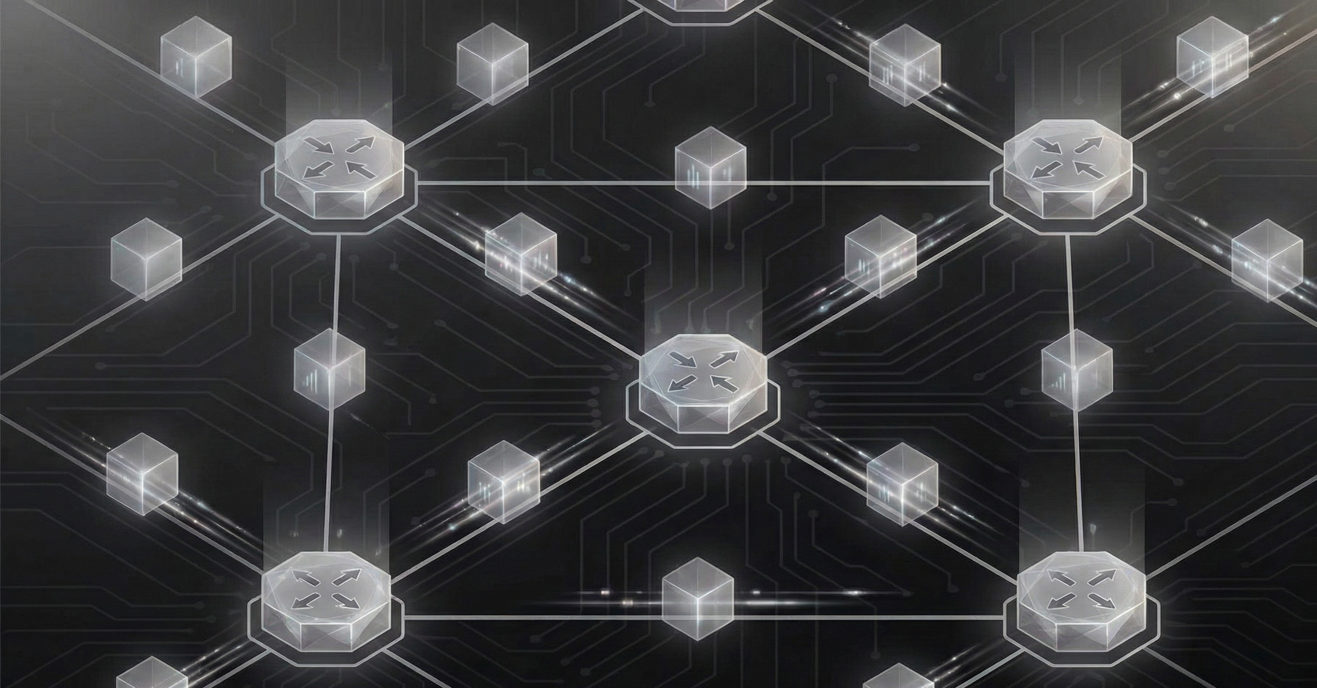
Routers: What They Do and Why They Exist
Your laptop doesn’t know how to reach Google. It doesn’t know the path it needs to take to send an email, your friend’s Minecraft server, or the DNS resolver that turns “gnu.foo” into an IP address. Your laptop knows one thing: the address of its default gateway1. That gateway is a router. And that router knows a little more than your laptop does—just enough to get the packet one step closer to where it needs to go.
That’s the fundamental responsibility a router takes on. It moves packets between networks that would otherwise have no way to communicate. Every network you have ever used, whether that be at home, in the office, on campus, or in a data center, depends on at least one.
The Problem Routers Solve
To understand routers, you need to understand the problem they exist to solve.
Imagine a small office with ten computers plugged into a switch. By nature of a switch these computers have no problem talking to one another directly. The switch learns which device is connected to which port, and it forwards frames accordingly using MAC addresses—the hardware addresses burned into each device’s network interface2.
This works just fine within a single network. But what happens when one of those computers needs to reach a server on the other side of the building? Or on the other side of the planet?
Switches don’t know how to handle that. They operate at Layer 2 of the OSI model: the Data Link layer. They understand MAC addresses and, for the purposes of forwarding, not much else3. They have no concept of “your network” versus “some other network.” A switch is happy as a clam to forward frames within its local segment, but it has no mechanism to send traffic beyond it.
That’s where routers come in. Switches handle the local conversation; routers handle everything else.
What a Router Actually Does
A router operates at Layer 3—the Network layer—of the OSI model. Where a switch makes forwarding decisions based on MAC addresses, a router makes its forwarding decisions based on IP addresses4. And instead of forwarding frames within a single network, it forwards packets between different networks.
Here’s the process, stripped to its essentials:
- A packet arrives on one of the router’s interfaces.
- The router examines the destination IP address in the packet header.
- It consults its routing table5—a list of known networks and the path to take to reach them.
- It decrements the TTL field in the IP header by one6.
- It rewrites the Layer 2 header—replacing the source and destination MAC addresses to reflect the next hop—and forwards the packet out of the appropriate interface.
Pay attention to step 5. This is a subtle detail that separates routing from switching on an exam question. A switch forwards a frame without rewriting the source or destination MAC addresses7. A router strips the incoming frame, makes a Layer 3 forwarding decision, and rebuilds a new frame for the outgoing network segment. The IP addresses (Layer 3) stay the same end to end8, but the MAC addresses (Layer 2) change at every hop.
That’s it. Every router on the planet does this. The complexity comes from how the routing table gets built and how the “best path” is determined—but those are topics for later posts in this series. For now, just know the fundamental operations: receive, look up, decrement TTL, re-encapsulate, forward.
The Post Office Analogy
Think of a router like a regional mail sorting facility. A letter arrives. The mail people don’t care about what’s in the letter. All they care about is destination address on the envelope. Based on that address, they determine which truck the letter goes on next. The truck takes the letter to the next facility, where the process repeats, until the letter reaches its final destination.
Routers do the same thing with packets. Each router doesn’t need to know the entire path to the destination. It only needs to know the next hop; the next router (or final destination) that gets the packet closer to where it’s going9.
Routers vs. Switches vs. Hubs
These three devices get conflated constantly, especially by those first exploring networking. They shouldn’t be. They operate at different layers and solve different problems.
Hubs (Layer 1)
A hub is the simplest networking device you’ll encounter—and the dumbest. As Michael Scott once said, “keep it simple stupid.” A hub takes that advice to its logical extreme: a signal comes in on one port, and the hub repeats it out every other port. No intelligence. No addressing. Every device connected to a hub sees every frame, whether it was meant for that device or not. Hubs are obsolete. They may have worked back in the early days of TCP/IP, but if you encounter one in the wild today, something has gone wrong.
Switches (Layer 2)
A switch is smarter. It learns which MAC addresses are reachable on which ports and forwards frames only where they need to go10. This allows for separate collision domains11—a massive improvement over hubs. But a switch still only operates within a single network. It doesn’t know what an IP address is12.
Routers (Layer 3)
A router connects different networks. It reads IP addresses, makes forwarding decisions based on its routing table, and creates separate broadcast domains on each of its interfaces. When a device on Network A needs to reach a device on Network B, a router is what makes that possible.
The Routing Table
I won’t go too deep into routing tables here, as Parts 33 and 34 cover them in their entirety. But you need to understand the concept now, because the routing table is the router’s brain.
A routing table is a list of entries, each one saying: “Hey! If you want to reach network X, send the packet out interface Y toward next-hop Z.” These entries get into the table through one of three mechanisms:
- Directly connected networks
- The router automatically knows about networks attached to its own interfaces.
- Like how you instinctively know where your hands and feet are without thinking about it. You don’t need to be told; the connection is direct and automatic.
- The router automatically knows about networks attached to its own interfaces.
- Static routes
- An administrator manually tells the router: “To reach this network, go through that next hop.”
- Like written directions taped to your dashboard: “To get to the warehouse, turn left at Main Street.” Someone had to write them down, and those instructions will remain the same unless you update them manually.
- An administrator manually tells the router: “To reach this network, go through that next hop.”
- Dynamic routing protocols
- Protocols like OSPF, EIGRP13, or BGP allow routers to discover routes by talking to neighboring routers and exchanging information automatically.
- Like using Waze for real-time traffic updates. If Waze lets you know that there was a Unicorn sighting on the highway and traffic is backed up, you immediately learn a new route—and if conditions change again, you’ll hear about that too.
- Protocols like OSPF, EIGRP13, or BGP allow routers to discover routes by talking to neighboring routers and exchanging information automatically.
When a packet arrives, the router checks the destination IP against its table, finds the best match, and forwards accordingly. If there’s no match, i.e. no route exists, the packet is dropped14.
Interfaces: Where Networks Meet
A router’s power comes from the fact that it sits between networks. Each of its interfaces connects to a different network, and each interface has its own IP address on that network.
Consider a router with two interfaces.
- Interface 1 has IP address
192.168.1.1and connects to Network A (192.168.1.0/24) - Interface 2 has IP address
10.0.0.1and connects to Network B (10.0.0.0/24).
A device on Network A with address 192.168.1.50 wants to reach a device on Network B at 10.0.0.25. Here’s what happens:
- The source device sees that
10.0.0.25is not on its local network (192.168.1.0/24). - It sends the packet to its default gateway, i.e. the router, at
192.168.1.1. - The router receives the packet on Interface 1, checks the routing table, and finds that
10.0.0.0/24is directly connected on Interface 2. - The router forwards the packet out Interface 2 to
10.0.0.25.
Two networks. One router. That’s the fundamental concept.
Why This Matters
Routers are what make the internet an internet. The word “internet” literally means “interconnected networks.” Without routers, every network would exist in isolation. Your home network couldn’t reach your ISP. Your ISP couldn’t reach the backbone. The backbone couldn’t reach the data center hosting the site you’re reading this on.
Every time you load a web page, your packets traverse multiple routers. Each one makes an independent forwarding decision—consulting its own routing table, choosing the best next hop, and passing the packet along. This decentralized, hop-by-hop forwarding model is what allows the internet to scale to billions of devices without any single point of control.
The internet protocol—IP, defined in RFC 791—was designed with this model in mind. Routers are the physical embodiment of that design.
Key Takeaways
- Routers forward packets between different networks: They operate at Layer 3 of the OSI model and use IP addresses to make forwarding decisions.
- The routing table is the core data structure: Every forwarding decision a router makes comes from consulting its routing table—a list of known networks and how to reach them.
- Routers create broadcast domain boundaries: Each router interface connects to a separate network, isolating broadcast traffic between them.
- Hubs, switches, and routers solve different problems: Hubs repeat signals. Switches forward frames within a network. Routers forward packets between networks. These terms are not interchangeable.
- The internet is routers, all the way down: The hop-by-hop forwarding model that routers implement is the core mechanism that allows the internet to function at scale.
In Part 3, we look at the router’s Layer 2 counterpart, switches, and explore the difference between Layer 2 and Layer 3 switching.
References
- Plummer, D. (1982). An Ethernet Address Resolution Protocol. RFC 826, IETF. Link
- Postel, J. (1981). Internet Protocol. RFC 791, IETF. Link
- Postel, J. (1981). Internet Control Message Protocol. RFC 792, IETF. Link
- Moy, J. (1998). OSPF Version 2. RFC 2328, IETF. Link
- Nichols, K., Blake, S., Baker, F., & Black, D. (1998). Definition of the Differentiated Services Field (DS Field) in the IPv4 and IPv6 Headers. RFC 2474, IETF. Link
- Srisuresh, P. & Egevang, K. (2001). Traditional IP Network Address Translator (Traditional NAT). RFC 3022, IETF. Link
- Narten, T., Nordmark, E., Simpson, W., & Soliman, H. (2007). Neighbor Discovery for IP version 6 (IPv6). RFC 4861, IETF. Link
- Rekhter, Y., Li, T., & Hares, S. (2006). A Border Gateway Protocol 4 (BGP-4). RFC 4271, IETF. Link
- Savage, D., Ng, J., Moore, S., Slice, D., Paluch, P., & White, R. (2016). Cisco’s Enhanced Interior Gateway Routing Protocol (EIGRP). RFC 7868, IETF. Link
- Deering, S. & Hinden, R. (2017). Internet Protocol, Version 6 (IPv6) Specification. RFC 8200, IETF. Link
- Cisco Systems. (2024). How Does a Router Work? Cisco. Link
- Cisco Systems. (2024). CCNA Exam Topics (200-301 v1.1). Cisco Learning Network. Link
- IEEE Standards Association. (2022). IEEE 802.3 — Ethernet. IEEE. Link
- IEEE Standards Association. (2022). IEEE 802.1Q — Bridges and Bridged Networks. IEEE. Link
Footnotes
-
Your laptop actually does know more than just its default gateway. Its TCP/IP stack is configured with its own IP address, subnet mask, DNS resolver(s), and MAC address, and it maintains its own local routing table—which can contain more than just a default route (think split-tunnel routes, link-local entries, etc.). The laptop makes the first routing decision: it checks the destination IP against its local routing table to determine whether the target is on-link—reachable directly on the local segment without a router—or off-link. For most cases, this comes down to a subnet mask comparison, i.e. same subnet = on-link, but on-link determination is actually a function of the host’s routing table and—in v6—RA flags (the L-flag in NDP Prefix Information options), not strictly subnet membership. A host can have an explicit on-link route to a prefix that doesn’t match its own subnet, and conversely, overlay networks (VXLAN, GRE) can make same-subnet hosts traverse routers at the underlay. Only if the destination is off-link does the laptop forward to the default gateway. But for understanding why routers exist, the simplification holds—your laptop delegates everything beyond the local segment to the router. For the curious: NDP RA flags & overlay behavior are CCNP ENCOR territory. You don’t need them for the CCNA. ↩
-
MAC addresses are technically modifiable in software, often referred to as MAC spoofing, and modern operating systems randomize them by default on Wi-Fi to limit tracking. A MAC address is 48 bits: the first 24 are the OUI (Organizationally Unique Identifier), assigned to the manufacturer, and the last 24 bits identify the specific device. IPv6 defines a method called EUI-64 to derive an interface identifier from the MAC address for stateless address autoconfiguration (SLAAC), but in practice most modern operating systems now generate randomized interface IDs by default (per RFC 8981, formerly RFC 4941) to avoid embedding the hardware MAC in the IPv6 address—a privacy concern that parallels Wi-Fi MAC randomization. For the purposes of understanding switches, think of MAC addresses as a device’s permanent hardware identifier, but know that port security exists precisely because MACs can be spoofed. MAC behavior will be re-visited in Part 20. ↩
-
Managed Layer 2 switches handle quite a bit beyond MAC-based frame forwarding—VLANs (part 21), STP (Part 27-28), EtherChannel, LLDP, and CDP (Part 25), DHCP snooping, Dynamic ARP Inspection, port security, and IGMP snooping, among other things. But none of these give the switch the ability to route packets between networks. The core point stands: a Layer 2 switch cannot get a packet from Network A to Network B. For the curious: Advanced STP tuning like MST is covered within CCNP ENCOR. ↩
-
Routers don’t ignore MAC addresses; they absolutely use them. When a router forwards a packet, it checks its ARP cache (a table mapping IP addresses to MACs) or performs an ARP (Address Resolution Protocol) request to resolve the next-hop IP address to a MAC address, then uses that MAC to build the outgoing Layer 2 frame. In IPv6, ARP doesn’t exist. It’s replaced entirely by NDP (Neighbor Discovery Protocol), which uses NS/NA messages to accomplish the same thing. The distinction here is that a router’s forwarding decision, i.e. which interface to send the packet out and which next hop to send it towards, is based on IP addresses. A switch’s forwarding decision is based on MAC addresses. That’s the point that needs to be understood for the differences between Layer 2 & 3 forwarding. For the curious: Proxy ARP—where a router answers ARP requests on behalf of hosts on another network—is covered in-depth within CCNP ENCOR. ↩
-
Strictly speaking, routers maintain two structures: a routing table (the Routing Information Base) built by the control plane from connected routes, static configuration, and dynamic protocols, and a forwarding table (the Forwarding Information Base) derived from the RIB and used for fast hardware lookups. The FIB is what the router actually consults per-packet in the data plane. At the CCNA level, Cisco treats the RIB and FIB as synonymous and refers to both as “the routing table.” I will use the term as they do to match exam terminology. For the curious: The RIB/FIB split and CEF (Cisco Express Forwarding) is covered within CCNP ENCOR. ↩
-
TTL prevents packets from looping endlessly within a network. Each router decrements it by one; when it hits zero, the packet is discarded and an ICMP Type 11 (“Time Exceeded”) message is sent back to the source. This is actually exactly how
tracerouteworks—it sends packets with incrementally increasing TTL values to discover each hop along the path. v6 renames this field Hop Limit, but the behavior is identical. Different operating systems set different default TTLs, which can be of use for OS fingerprinting. For the curious: A security mechanism built on TTL (GTSM), which rejects packets with low TTL values to protect BGP sessions from spoofing, is a CCNP ENARSI concept that you’ll encounter in studying BGP hardening. ↩ -
A switch doesn’t rewrite source or destination MAC addresses, but it can modify other parts of the frame. Most notably, when a frame moves between an access port and a trunk port, the switch inserts or strips the 4-byte 802.1Q VLAN tag in the Ethernet header. On trunk ports, frames belonging to the native VLAN are typically sent untagged, while all other VLAN frames carry the tag (this is a common source of misconfiguration and security issues). QoS policies can also rewrite the CoS (Class of Service) bits in the PCP field within the tag. The key distinction from routing is that a switch passes the original source and destination MAC addresses; a router replaces both. For the curious: Actually configuring QoS policies on switches is CCNP ENCOR, as is Q-in-Q (802.1ad). ↩
-
This is true in basic routing, but NAT breaks this model. There are three common types: Static maps one private IP to one public IP, Dynamic maps from a pool of public addresses, and PAT (Port Address Translation, also called NAT overload) maps many private IPs to a single public address by multiplexing on port numbers—most common within home routers. A NAT device rewrites the source address and sometimes the destination as the packet passes through, so the far end sees a different IP than the one that originally sent the packet. We’ll cover NAT in detail in Part 43. For the curious: NAT/PAT troubleshooting at scale and NAT64 are CCNP ENCOR topics. ↩
-
This analogy simplifies things by a large factor, but is useful in understanding the underlying flow of data. Routers do not guarantee delivery or ordering—that’s TCP’s job (we’ll cover TCP versus UDP in Part 11). And unlike a mail facility that ignores the contents of a letter, routers indeed can inspect certain header fields beyond the destination IP: the DSCP (Differentiated Services Code Point) field in the header tells the router how to prioritize the packet, e.g. voice traffic might get expedited forwarding while bulk downloads get best-effort treatment. But the core forwarding logic—read the destination address, pick the next step—holds regardless of QoS. For the curious: Actually implementing QoS policies and per-flow load balancing via CEF land under CCNP ENCOR. ↩
-
This is the ideal case. In practice, switches don’t always forward frames only to the specific destination port. When a switch receives a frame destined for a MAC address it has yet to learn, an unknown unicast, it floods the frame out all ports in the VLAN except the one it arrived on, behavior that’s functionally identical to a hub for that individual frame. Broadcast frames and multicast frames are also flooded by default (IGMP snooping can limit multicast flooding). The switch’s MAC table has a finite size and entries age out after a timer (defaults will vary based on provider, but Cisco has a default of 300 seconds); if a table overflows, whether from a large network or a CAM overflow attack, the switch floods all traffic, effectively becoming a hub. We’ll go over MAC learning, aging, flooding, and the MAC address table as a whole in Part 20. ↩
-
On modern full-duplex switch ports, which is basically all of them at this point, collisions cannot occur, and CSMA/CD is disabled entirely. The “separate collision domains per port” framing matches CCNA-standard terminology and holds true historically for half-duplex connections, but in practice, full-duplex has made the collision domain more theory than anything else. That is not to say you should not be familiar, as duplex mismatch is a classic troubleshooting scenario that causes late collisions and degraded performance. Auto-negotiation (IEEE 802.3u) determines speed and duplex between connected devices; when it fails or is misconfigured, mismatches occur. ↩
-
This is true for a traditional Layer 2 switch. Layer 3 switches do understand IP addresses and can perform routing. This typically occurs across VLANs using SVIs (Switched Virtual Interfaces), which act as the default gateway for each VLAN. This is called inter-VLAN routing, and for the CCNA you’ll encounter two approaches: router-on-a-stick (a physical router with sub-interfaces, one per VLAN, connected via trunk port) and SVI-based routing on a Layer 3 switch (no external router needed). L3 switches perform routing in hardware using ASICs, making them significantly faster than traditional routers for inter-VLAN traffic. We’ll cover that in Part 3. For the curious: How L3 switches actually achieve wire-speed routing in hardware, i.e. CEF, TCAM, distributed forwarding, is CCNP ENCOR. ↩
-
EIGRP (Enhanced Interior Gateway Routing Protocol) was Cisco-proprietary until 2016, when Cisco published its basic operation as RFC 7868 (Informational). However, that RFC covers only the core protocol. Advanced features like stub routing and route filtering remain vendor-locked to Cisco, and in practice EIGRP is still overwhelmingly a Cisco-only protocol. For context, these three protocols represent different algorithmic families: OSPF is a link-state protocol (every router builds a complete topology map), EIGRP is an advanced distance-vector protocol (routers share only route information with neighbors, using DUAL for loop-free path selection), and BGP is a path-vector protocol (routes carry the full AS-path, primarily used between autonomous systems). When multiple protocols offer routes to the same destination, the router uses AD to choose: EIGRP internal (90) beats OSPF (110) beats EIGRP external (170) beats iBGP (200), among others. In a vendor-agnostic context, OSPF and BGP are the standard go-tos. I mention EIGRP because it appears on the CCNA exam. For the curious: EIGRP versus OSPF comparison and BGP path selection are covered under CCNP ENCOR. EIGRP’s DUAL algorithm, stub routing, and BGP troubleshooting go deeper into CCNP ENARSI. ↩
-
Unless…the router has a default route. Because the prefix length of a default route is 0, any specific route wins over the default via longest prefix match (a /24 route is more specific than /0). For Cisco IOS, your default route will appear as the Gateway of last resort in the routing table output. Default routes can be configured statically, learned via DHCP, or injected by dynamic routing protocols. A related concept is the floating static route—a static route configured with a higher AD than the dynamic route, so it only activates if the dynamic route disappears. This will be covered more in-depth in Part 36. ↩
Comments
Loading comments...
Leave a comment